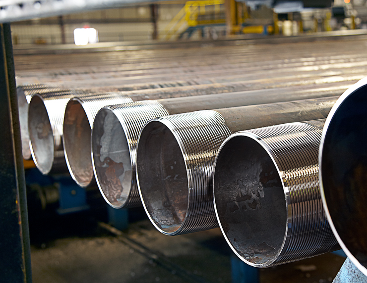
Oil casing production process

Fecha:2023-06-06Vista:324Etiquetas:Proceso de producción de revestimiento de aceite, inspección de revestimiento de aceite, proceso, fábrica de OCTG

Inspección de la carcasa de aceite en la fábrica


1.1 Frecuencia de inspección

Tabla 1.1 Supervisión de calidad y plan de muestreo

Batch Range N

Sample Size n

Number of Acceptable Judgments Ac


Number of Unqualified Judgments Re


9 ~ 15

3

0

1

16 ~ 25

5

0

1

26 ~ 50

8

0

1

51 ~ 90

13

1

2

91 ~ 150

20

2

3

151 ~ 280

32

3

4

281 ~ 500

50

5

6

501 ~ 1200

80

7

8

1201 ~ 3200

125

10

11

3201 ~ 10000

200

14

15


1.2  artículos de inspección

  • 1.2.1 Diámetro exterior
    Utilice un pie de rey calibrado para medir los diámetros exteriores de los dos extremos y la mitad del tubo plano y los diámetros exteriores de los dos extremos del tubo ciego de acoplamiento en el plano perpendicular al eje del tubo, y registre los valores máximo y mínimo. .
    Si alguna de las tuberías muestreadas no cumple con los requisitos especificados, se tomarán otras 3 tuberías de este lote de tuberías para su medición. Si los tubos medidos nuevamente cumplen con los requisitos especificados, el lote de tubos es aceptable excepto por los tubos originales no calificados. Si alguna de las tuberías reinspeccionadas no cumple con los requisitos especificados, las tuberías restantes del lote se medirán una por una. Si un solo tubo no cumple con los requisitos especificados, se puede volver a probar después de cortar la cabeza.
    1.2.2 Espesor de pared
    Utilice un medidor de espesor ultrasónico certificado para medir el espesor de la pared en los extremos de la tubería y en el centro del cuerpo de la tubería, y registre los valores máximo y mínimo. Para tubos sin costura, la medición del espesor de pared de longitud total se debe realizar en la dirección de la espiral o en la dirección longitudinal; cada tubería se medirá al menos en tres posiciones en la cabeza, en el medio y en la cola, y se medirán cuatro puntos a lo largo de la circunferencia.
    La desviación local del espesor de pared de la tubería es de -10 %t.
    1.2.3 Longitud
    Use una cinta de acero calibrada para medir la longitud de la tubería. La longitud medida debe estar dentro del rango especificado. Cuando la tubería es larga
    Cuando la precisión es inferior a 30 m, la precisión de la cinta de acero es de ±0,03㎜.
    1.2.4 Rectitud
    (1) rectitud de longitud completa: tire de una cuerda (alambre) de un extremo de la tubería al otro y mida la altura de la cuerda de la tubería desviada de la línea recta; al verificar la rectitud de la longitud total, la altura de la cuerda desviada de la línea recta no debe exceder el 0,15% de la longitud total de la tubería;
    (2) Rectitud del extremo de la tubería: use una regla de al menos 1,83 m de largo en el lado del arco exterior del codo de la tubería y mida la distancia entre la regla de la curva y la superficie de la tubería. El hundimiento dentro de 1,5 m de cada extremo de la tubería no debe exceder los 2,5 mm.
    1.2.5 Cuerpo de la tubería (sin incluir los extremos de la tubería)
    Toda la superficie exterior del tubo se inspecciona visualmente en busca de defectos; si el tubo es visualmente defectuoso, la profundidad radial del defecto no debe exceder el 10 % del espesor de pared especificado.
    1.2.6 Extremos de tubería
    (1) Realice una inspección visual de la superficie exterior dentro de al menos 450 mm desde el extremo de la tubería;
    ⑵ Tuberías sin engrosamiento: se debe realizar una inspección visual en la superficie interna dentro de un rango de al menos 2,5 D o 450 mm (lo que sea menor) desde el extremo de la tubería;
    (3) Tubería engrosada: inspeccione visualmente la superficie interna dentro de la longitud de la porción engrosada desde el extremo de la tubería (incluida la zona de transición engrosada).
    1.2. 7 Tratamiento de defectos
    Varios defectos que afectan el desempeño de la tubería encontrados en la inspección del cuerpo de la tubería o del extremo de la tubería, tales como picaduras, grietas, pliegues, golpes, magulladuras, estrías, delaminación, rayitas, etc., si la profundidad del defecto no Exceda el 10% del grosor de la pared del tubo completo, se puede eliminar mediante el esmerilado manual, y se puede realizar una transición suave entre la parte de esmerilado y el cuerpo del tubo.
    Durante la inspección, si se encuentra que la profundidad del defecto del cuerpo de la tubería excede el 10 % del espesor total de la pared del cuerpo de la tubería, la tubería debe considerarse no calificada; si se encuentran tales defectos excesivos en el extremo de la tubería, se debe marcar y eliminar mecánicamente.

Oil casing inspection

2.Flujo de proceso de la máquina de espesamiento
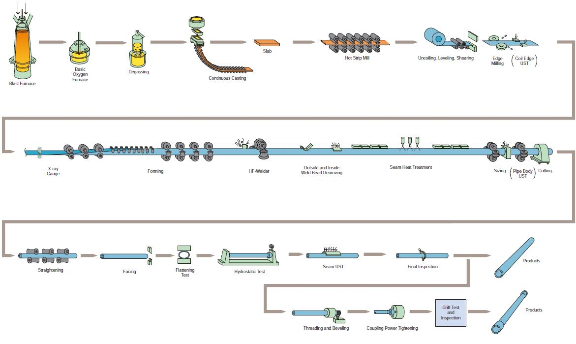
  • 2.1 Flujo de proceso
    Alimentación → calentamiento → espesamiento → inspección → molienda y normalización → inspección y almacenamiento del producto terminado

Oil casing production process

    • 2.2 Feeding
    ⑴ The thickening department issues a raw material requisition to use the one-way raw material warehouse for material requisition, and can only be requisitioned with the consent of the raw material warehouse;
    ⑵ After the raw materials are taken back, the material loader should first confirm the raw material steel grade, specification, length and various measured dimensions of the thickened pipe, and check whether the pipe body has pits, scratches, (the degree of scratches is less than or equal to the raw material wall Thickness 10%) problems such as bending, concentricity, etc., if there are problems, they should be handed over to the quality inspection department, and the raw materials can only be loaded after passing the inspection.
    • 2.3 Heating
    ⑴ Before starting the machine, the operator first turns on the power of the equipment to ensure that all equipment can be started normally, check whether there is water in the cooling water tank, and whether there is water pressure in the heating intermediate frequency furnace (greater than or equal to 0.2mpa). Secondly, do a good job of lubricating the guide column of the thickening machine and the track of the heating trolley, and finally start the heating intermediate frequency furnace to check whether the heating can be started normally;
    ⑵ During production, the material is transported to the heating intermediate frequency furnace through the stepping mechanism for heating. The temperature of the first few (usually 3 to 5) pipes of various specifications should be controlled at 1050°C to 1100°C, the visual effect is white at the end of the tube. Then the heating temperature is gradually lowered, controlled at 950°C to 1050°C, and the visual effect is that the end of the tube is reddish and slightly white.
    • 2.4 Thickened

    ⑴ When thickening pipes of various specifications, it is necessary to select molds of corresponding sizes, check whether the specifications and integrity of the molds meet the production requirements, and install the molds correctly according to the operating procedures. The following table is the mold size required for thickening pipe materials of various specifications:

Table 2.1 60.3*4.83 (type: seamless/ERW; tempered/non-tempered)

Specification

pass

punch forming area size(mm )

punch forging surface siz(mm )

punch top to forging surface size(mm )

Thickening mold

length(mm )

moon bend

size(mm)

Clamping die

size(mm )

Dimensions of the thickening end of the thickening mold(mm)

60.3×4.83

first

51.0

63.0

≤300

500

50

650

64.2

secondary

51.0

66.5

250

500

50

650

67


Table 2.2 73.02*5.51 (type: seamless/ERW; tempered/non-tempered)

Specification

pass

punch forming area size(mm )

punch forging surface siz(mm )

punch top to forging surface size(mm )

Thickening mold

length(mm )

moon bend

size(mm)

Clamping die

size(mm )

Dimensions of the thickening end of the thickening mold(mm)

73.02×5.51

first

63.2

75.5

≤300

500

50

650

76.5

secondary

63.2

79.5

250

500

50

650

80.0


Table 2.3 88.9*6.45 (type: seamless/ERW; tempered/non-tempered)

Specification

pass

punch forming area size(mm )

punch forging surface siz(mm )

punch top to forging surface size(mm )

Thickening mold

length(mm )

moon bend

size(mm)

Clamping die

size(mm )

Dimensions of the thickening end of the thickening mold(mm)

88.9×6.45

first

77

92

≤300

500

50

650

92.7

secondary

77

96.5

250

500

50

650

96.5


Table 2.4 114.3*6.88 (type: seamless/ERW; tempered/non-tempered)

Specification

pass

punch forming area size(mm )

punch forging surface siz(mm )

punch top to forging surface size(mm )

Thickening mold

length(mm )

moon bend

size(mm)

Clamping die

size(mm )

Dimensions of the thickening end of the thickening mold(mm)

114.3×6.88

first

101.5

107.5

≤300

500

50

650

118.5

secondary

101.5

121.1

250

500

50

650

122.5


⑵ At the beginning of production, it is very important to control the spraying time of cooling water, because the production of qualified pipe molds and punches requires a certain temperature, and the length of water spraying time directly affects the temperature of the molds and punches, thus affect the quality of the pipe. Therefore, when producing the first few pipes, the water spray time should be controlled between 7s and 8s to keep the punch and die at a certain temperature, and then the water spray time will be extended as the temperature of the die and punch rises. The control range is generally within Between 10s and 12s. The air injection time is mainly determined by the air flow rate. It is enough to dry the cooling water in the mold of the lower mold. Generally, it is controlled between 1s and 3s;


⑶ In order to produce qualified pipes, the mold punch must ensure a certain temperature. Generally, the temperature can be judged from the effect of graphite coating on the mold. When graphite water is applied to the mold and the punch cannot stick to the mold surface immediately, then It proves that the mold temperature is too low and the cooling time needs to be reduced. When the graphite is coated with the mold punch, blisters occur or the graphite directly slides off, the mold temperature is too high, and the cooling time needs to be increased. The optimum temperature is considered to be when the graphite is able to stick to the surface of the die punch and start to dry immediately after coating.


related suggestion
Chemical composition of various steel grades of api 5ct oil casing

Product requirements for J55 and K55 steel grade oil casing in API 5CT

specifications of API 5CT Grade N80 oil casing

Guess what you want to see

Grades and Specifications for API 5L Pipe

Oil Casing Specification Table


Solicitud de cotización

Si tiene necesidades comerciales o consultas, puede dejarnos un mensaje. le responderemos lo antes posible.