Oil casing production process

Date:2023-06-06View:494Tags:Oil casing production process,Oil casing inspection,process,OCTG factory

Oil casing inspection at the factory


1.1 Inspection frequency


Table 1.1 Quality supervision and sampling plan

Batch Range N

Sample Size n

Number of Acceptable Judgments Ac


Number of Unqualified Judgments Re


9 ~ 15

3

0

1

16 ~ 25

5

0

1

26 ~ 50

8

0

1

51 ~ 90

13

1

2

91 ~ 150

20

2

3

151 ~ 280

32

3

4

281 ~ 500

50

5

6

501 ~ 1200

80

7

8

1201 ~ 3200

125

10

11

3201 ~ 10000

200

14

15


1.2 Inspection items

  • 1.2.1 Outer diameter
Use a calibrated vernier caliper to measure the outer diameters of the two ends and the middle of the flat pipe and the outer diameters of the two ends of the coupling blank pipe in the plane perpendicular to the pipe axis, and record the maximum and minimum values.
If any of the pipes sampled does not meet the specified requirements, another 3 pipes shall be taken from this batch of pipes for measurement. If the re-measured pipes meet the specified requirements, the batch of pipes is acceptable except for the original unqualified pipes. If any of the re-inspected pipes fails to meet the specified requirements, the remaining pipes in the batch shall be measured one by one. If a single pipe does not meet the specified requirements, it can be re-tested after cutting the head.
  • 1.2.2 Wall thickness
Use a certified ultrasonic thickness gauge to measure the wall thickness at the pipe ends and in the middle of the pipe body, and record the maximum and minimum values. For seamless pipes, the full-length wall thickness measurement shall be carried out in the spiral direction or in the longitudinal direction; each pipe shall be measured at least three positions at the head, middle and tail, and four points shall be measured along the circumference.
The local deviation of the wall thickness of the pipe is -10 %t.
  • 1.2.3 Length
Use a calibrated steel tape to measure the length of the pipe. The measured length should be within the specified range. When the pipe is long
When the accuracy is less than 30m, the accuracy of the steel tape is ±0.03㎜.
  • 1.2.4 Straightness
(1) Full-length straightness: Pull a rope (wire) from one end of the pipe to the other, and measure the chord height of the pipe deviated from the straight line; when checking the full-length straightness, the chord height deviated from the straight line shall not exceed 0.15 of the total length of the pipe %;
(2) Pipe end straightness: Use a ruler at least 1.83m long on the outer arc side of the pipe bend, and measure the distance between the bend ruler and the pipe surface. The sag within 1.5m of each end of the pipe shall not exceed 2.5mm.
  • 1.2.5 Pipe body (not including pipe ends)
The entire outer surface of the tube is inspected visually for defects; if the tube is visually defective, the radial depth of the defect shall not exceed 10 % of the specified wall thickness.
  • 1.2.6 Pipe ends
(1) Carry out a visual inspection of the outer surface within at least 450mm from the pipe end;
⑵ Non-thickening pipes: Visual inspection is to be carried out on the inner surface within a range of at least 2.5D or 450 mm (whichever is less) from the pipe end;
(3) Thickened pipe: visually inspect the inner surface within the length of the thickened portion from the end of the pipe (including the thickened transition zone).
  • 1.2. 7 Defect handling
Various defects that affect the performance of the pipe found in the inspection of the pipe body or pipe end, such as pits, cracks, folds, bumps, bruises, gouges, delamination, hairlines, etc., if the depth of the defect does not exceed the entire pipe 10% of the wall thickness can be removed by manual grinding, and the smooth transition between the grinding part and the pipe body can be made.

During the inspection, if the depth of the pipe body defect is found to exceed 1 0 % of the entire pipe body wall thickness, the pipe should be judged as unqualified; if such excessive defects are found at the pipe end, it should be marked and mechanically removed .
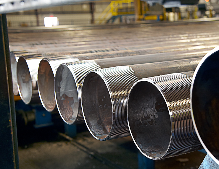
Oil casing inspection

2.Process flow of thickening machine

  • 2.1 Process flow

Feeding → heating → thickening → inspection → grinding and normalizing → finished product inspection and storage
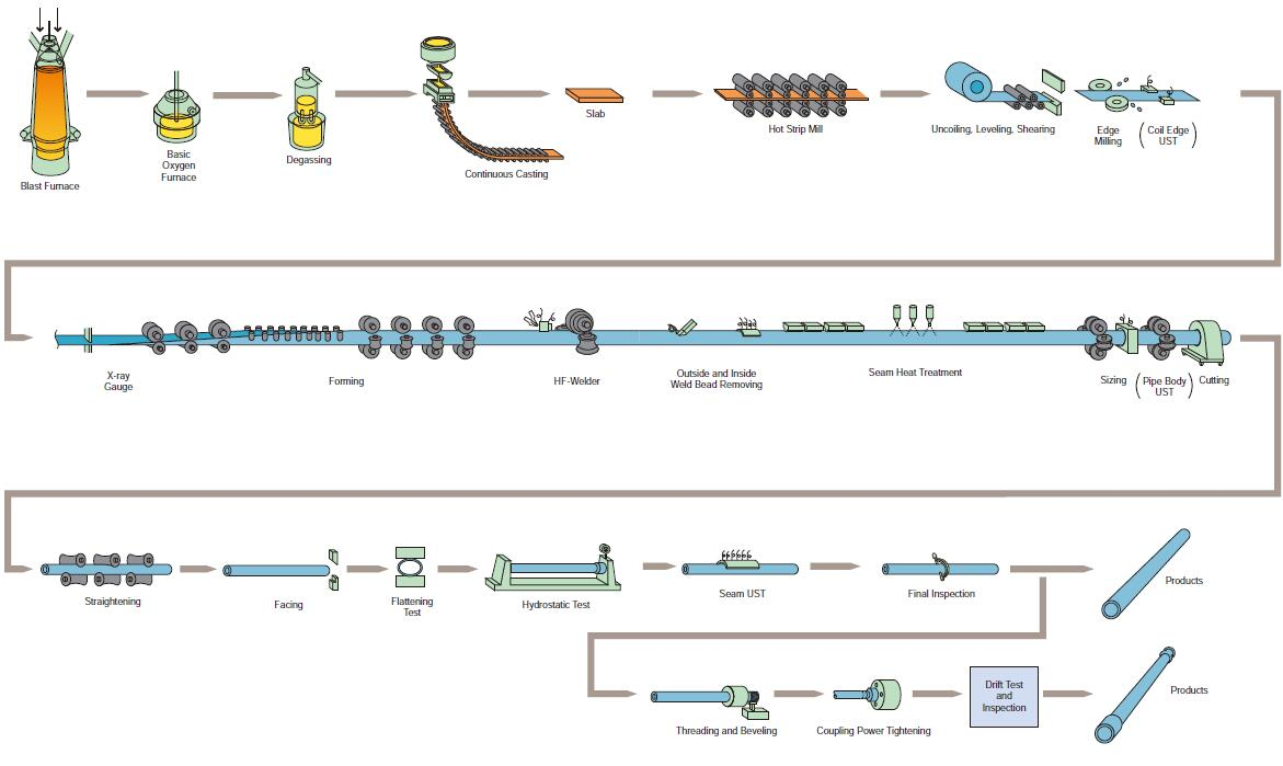
Oil casing production process

  • 2.2 Feeding
⑴ The thickening department issues a raw material requisition to use the one-way raw material warehouse for material requisition, and can only be requisitioned with the consent of the raw material warehouse;
⑵ After the raw materials are taken back, the material loader should first confirm the raw material steel grade, specification, length and various measured dimensions of the thickened pipe, and check whether the pipe body has pits, scratches, (the degree of scratches is less than or equal to the raw material wall Thickness 10%) problems such as bending, concentricity, etc., if there are problems, they should be handed over to the quality inspection department, and the raw materials can only be loaded after passing the inspection.
  • 2.3 Heating
⑴ Before starting the machine, the operator first turns on the power of the equipment to ensure that all equipment can be started normally, check whether there is water in the cooling water tank, and whether there is water pressure in the heating intermediate frequency furnace (greater than or equal to 0.2mpa). Secondly, do a good job of lubricating the guide column of the thickening machine and the track of the heating trolley, and finally start the heating intermediate frequency furnace to check whether the heating can be started normally;
⑵ During production, the material is transported to the heating intermediate frequency furnace through the stepping mechanism for heating. The temperature of the first few (usually 3 to 5) pipes of various specifications should be controlled at 1050°C to 1100°C, the visual effect is white at the end of the tube. Then the heating temperature is gradually lowered, controlled at 950°C to 1050°C, and the visual effect is that the end of the tube is reddish and slightly white.
  • 2.4 Thickened

⑴ When thickening pipes of various specifications, it is necessary to select molds of corresponding sizes, check whether the specifications and integrity of the molds meet the production requirements, and install the molds correctly according to the operating procedures. The following table is the mold size required for thickening pipe materials of various specifications:

Table 2.1 60.3*4.83 (type: seamless/ERW; tempered/non-tempered)

Specification

pass

punch forming area size(mm )

punch forging surface siz(mm )

punch top to forging surface size(mm )

Thickening mold

length(mm )

moon bend

size(mm)

Clamping die

size(mm )

Dimensions of the thickening end of the thickening mold(mm)

60.3×4.83

first

51.0

63.0

≤300

500

50

650

64.2

secondary

51.0

66.5

250

500

50

650

67


Table 2.2 73.02*5.51 (type: seamless/ERW; tempered/non-tempered)

Specification

pass

punch forming area size(mm )

punch forging surface siz(mm )

punch top to forging surface size(mm )

Thickening mold

length(mm )

moon bend

size(mm)

Clamping die

size(mm )

Dimensions of the thickening end of the thickening mold(mm)

73.02×5.51

first

63.2

75.5

≤300

500

50

650

76.5

secondary

63.2

79.5

250

500

50

650

80.0


Table 2.3 88.9*6.45 (type: seamless/ERW; tempered/non-tempered)

Specification

pass

punch forming area size(mm )

punch forging surface siz(mm )

punch top to forging surface size(mm )

Thickening mold

length(mm )

moon bend

size(mm)

Clamping die

size(mm )

Dimensions of the thickening end of the thickening mold(mm)

88.9×6.45

first

77

92

≤300

500

50

650

92.7

secondary

77

96.5

250

500

50

650

96.5


Table 2.4 114.3*6.88 (type: seamless/ERW; tempered/non-tempered)

Specification

pass

punch forming area size(mm )

punch forging surface siz(mm )

punch top to forging surface size(mm )

Thickening mold

length(mm )

moon bend

size(mm)

Clamping die

size(mm )

Dimensions of the thickening end of the thickening mold(mm)

114.3×6.88

first

101.5

107.5

≤300

500

50

650

118.5

secondary

101.5

121.1

250

500

50

650

122.5


⑵ At the beginning of production, it is very important to control the spraying time of cooling water, because the production of qualified pipe molds and punches requires a certain temperature, and the length of water spraying time directly affects the temperature of the molds and punches, thus affect the quality of the pipe. Therefore, when producing the first few pipes, the water spray time should be controlled between 7s and 8s to keep the punch and die at a certain temperature, and then the water spray time will be extended as the temperature of the die and punch rises. The control range is generally within Between 10s and 12s. The air injection time is mainly determined by the air flow rate. It is enough to dry the cooling water in the mold of the lower mold. Generally, it is controlled between 1s and 3s;


⑶ In order to produce qualified pipes, the mold punch must ensure a certain temperature. Generally, the temperature can be judged from the effect of graphite coating on the mold. When graphite water is applied to the mold and the punch cannot stick to the mold surface immediately, then It proves that the mold temperature is too low and the cooling time needs to be reduced. When the graphite is coated with the mold punch, blisters occur or the graphite directly slides off, the mold temperature is too high, and the cooling time needs to be increased. The optimum temperature is considered to be when the graphite is able to stick to the surface of the die punch and start to dry immediately after coating.


related suggestion
• Chemical composition of various steel grades of api 5ct oil casing

• Product requirements for J55 and K55 steel grade oil casing in API 5CT

• specifications of API 5CT Grade N80 oil casing

Guess what you want to see

• Grades and Specifications for API 5L Pipe

Oil Casing Specification Table


Request A Quote?

If you have business needs or inquiries, you can leave a message to us. We'll get back to you as soon as possible.
We use cookies and other tracking technologies to improve your browsing experience on our website, to show you personalized content and targeted ads, to analyze our website traffic, and to understand where our visitors are coming from.