| Product: | Concrete Coated Pipe, Concrete Weight Coating |
| Application: | Used for natural gas, petroleum, water & sewage, and pipe systems |
| Size: | OD: 219mm~2020mm |
| WT: 5mm~25mm | |
| LENGTH: 4mtr, 6mtr, 12mtr, 18mtr, 21mtr | |
| Standard | DIN 30670, DIN 30671, DIN 30678, SY/T0413-2002 etc. |
| Pipe tape | Submerged Arc Welded (LSAW/SSAW), Electric Resistance Welded |
| End | Plain End/Bevelled End, Burr Removed |
| Coating Thickness | Three Layer Polyethylene Coating (2mm~4.5mm) |
| Packing | Waterproof Paper wrapped, Steel Strips |
Product:
Concrete Coated Pipe, Concrete Weight Coating
Application:
Used for natural gas, petroleum, water & sewage, and pipe systems
Size:
OD: 219mm~2020mm
WT: 5mm~25mm
LENGTH: 4mtr, 6mtr, 12mtr, 18mtr, 21mtr
Standard
DIN 30670, DIN 30671, DIN 30678, SY/T0413-2002 etc.
Pipe tape
Submerged Arc Welded (LSAW/SSAW), Electric Resistance Welded
End
Plain End/Bevelled End, Burr Removed
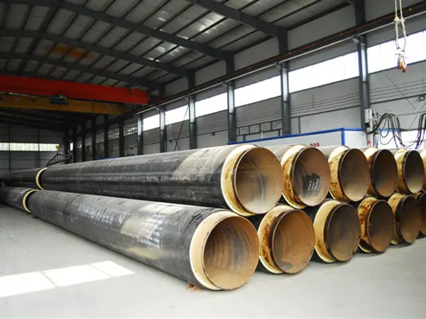
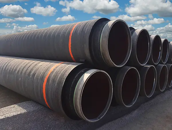
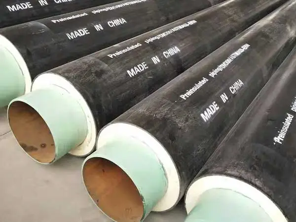
 Concrete Coating Pipe Introduction
 Dimensions Ranges for Concrete Coating Pipe
Mother pipe standards: API 5L Grade B to Grade 80. ISO 3183 Grade L245 to L555.
Diameter range: 6” to 60”
Pipe Thickness: SCH 20, SCH 40, SCH 80
Length: Up to 12 meters
Concrete Weight Coating Density
The concrete formulation can be tailored to any specified density specifications, normally are 140, 165, and 190 pounds per cubic foot, smaller or greater densities also applicable.
Density range: 1800-3450 kg/m3 (112-215 lbs/ft3)
Concrete compressive strength: From 3000 psi to 7200 psi. Up to 50 Mpa.
Concrete thickness: 1 inch to 8 inches. (25 mm to 200 mm)
Referred Standards
DNV-OS-F101: Submarine Pipeline Systems – SAWL 245, SAWL290, SAWL 320, SAWL 360, SAWL 415, SAWL 450, SAWL 485, SAWL 555
ISO 21809-5:2010: Petroleum and natural gas industries – External coatings for buried or submerged pipelines used in pipeline transportation systems – Part 5: External concrete coatings.
• ASTM C42 Standard Test Method for Obtaining and Testing Drilled Cores and Sawed Beams of Concrete
• ASTM C87 Test Methods for Effect of Impurities in Fine Aggregate on Strength of Mortar BS 1881 Methods of Testing Concrete
• ASTM C642 Standard Test Method for Specific Gravity, Absorption, and Voids in Hardened Concrete
• BS 3148 Test Methods for Water for Making Concrete
• BS 4449 Material Specification for Carbon Steel Bars for Concrete Reinforcement
• BS 4482 Hard Drawn Mild Steel Wire for the Reinforcement of Concrete
• BS 4483 Specification for Steel Fabric for the Reinforcement of Concrete
• ISO 4012 Test Specimen of Determination of Compressive Strength
Features of CWC pipe
CWC pipe consist of cement, water, aggregates and reinforcement materials, it’s advantage is to fix the pipeline stably performances and provides effective mechanical protection. Compared with other insulation type like pipe-in-pipe, CWC pipe is more efficient in saving cost, easy the pipeline installation and convenient the operations.
Benefits of Concrete Coating Pipe
• Mechanical protection and negative buoyancy
• Anti-corrosion protection
• Excellent Compatibility
• Long-term adhesion to steel
• Well suited to reel laying methods
• High resistance to cathodic disbondment
• And much more

Radiographic testing
Radiographic testing is performed by recording degrees of absorption of penetrating radiation throughout the pipe wall. This results in generating a latent image of the object being under consideration or examined on a film that is later on chemically treated to transform the latent image into a permanent shadow image of internal and external defects in the pipeline. High intensity of radiation passes through the defected area when compared to regions without defects. Finally, these radiographer images can be evaluated by either professionals or automated computer vision systems.
Low-frequency electromagnetic testing (LFET)
In this process, the inspection process is accomplished by placing two ends of the electromagnetic driver on the metal surface, and a sensor is placed in between the two ends of the driver. The driver is a source of emitting low frequency (3-40Hz) alternating current signal and the sensors detect the magnetic field develops between the two poles of the driver. The principle of this testing is, “flaws in the steel structure alter the magnetic field”, this alteration is recorded by the sensors in the form of amplitudes and variation in phase. If more flaws are found, the deviation in the magnetic signal will become wider and the sensors will record more shifts in the magnetic signal. Finally, the recorded signals transformed into a percentage of material loss by using numerical calculations.
Balanced field electromagnetic testing
This process the inspection of cylindrical storage tanks can be consummated by placing an electromagnetic probe near a metallic body. The divergence in the magnetic field is recorded; the vertical and horizontal sections of the signal are phase-shifted to reduce the noise in determining the magnetic field.
Longitudinal ultrasonic testing
In ultrasonic testing, a transducer emits high-frequency ultrasonic waves and propagates them across the material under investigation. Further, the transducers record the time lapse between the waves released and when the waves’ echoes are received back to the transducers. In case of any flaws the time duration between the released and echoed waves condensed (comparing the absence of any flaws in the material). In ultrasonic testing, the particles in the material under consideration oscillate in response to the energy present in the ultrasonic waves propagated through it. The direction of the oscillation of particles is in the longitudinal direction.
Shear wave ultrasonic testing
The working principle of shear wave ultrasonic testing is the same to that of longitudinal ultrasonic testing. The only difference is the movement of particles is perpendicular to the direction of sound/ultrasonic waves. SWUT is also called angle beam testing, as it is employed to find out the flaws’ dimensions and their depth in the material under consideration.


MATERIALS
All concrete coating materials shall be furnished by the CONTRACTOR and shall consist of Portland cement, aggregate, reinforcing steel and water. These materials shall conform to the following specifications.
Cement
Cement shall conform to ASTM C150, Type II, or approved equal and shall be stored in a manner that will satisfactorily protect it from the elements. Cement that has hardened, partially hardened, or become lumpy shall not be used. Test certificates from the cement manufacturer shall be presented to the COMPANY for all cement.
Water
Water shall be clean and free from injurious amounts of oil, acid, alkali, salt, organic material or other deleterious substances. Seawater or water from stagnant swamps or excavations shall not be used. The COMPANY reserves the right to require the CONTRACTOR to test the water and have the results approved by the COMPANY prior to its use in the concrete mixture.
Sand (Silica Type)
Sand used shall be round grained and shall be obtained by sieving. It shall be free of injurious amounts of salt, alkali, deleterious substances or organic impurities. Suitability of the natural sand for making concrete shall be determined in accordance with the requirements of ASTM C33. The sand shall be well graded to the following sieve sizes:
U.S. Standard %
Sieve SizePassive
4100
880‐100
1650‐80
3025‐55
505‐30
1000‐10
Aggregate
Well graded iron or barium ore shall be added to the aggregates to achieve the required density.
Concrete aggregates shall be clean, sound and free from injurious amounts of salt, alkali, organic impurities or other deleterious matter. Aggregates shall meet the requirements of ASTM C33. The aggregates shall be well graded to the following sieve sizes:
U.S. Standard %
Sieve Size Passive
3/8 in. 100
No. 4 80‐90
No. 16 40‐70
No. 50 10‐30
No. 100 0‐10
The aggregates shall be stored in a suitably graded area to ensure satisfactory draining of the stock pipe.
Reinforcing Steel
The reinforcement shall consist of a woven or welded wire mesh. Woven wire mesh shall be of the hexagonal type with extra longitudinal wires. Size of hexagonal mesh openings shall be 1.5 inches across the minimum dimensions. Welded wire mesh shall have openings of 1‐inch by 2‐inch.
The wire mesh shall be galvanized and the materials shall conform to ASTM A82, A90, A185 and A641 as applicable.
HuNan Province
+86-731-85648266
LiaoNing Province
+86-731-85648266
HeBei Province
+86-731-85648299
jiangsu Province
+86-731-85648299
TianJin City
Singapore
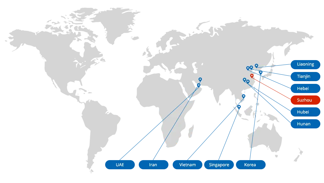
United Steel Industry As the most important steel pipe manufacturer and exporter in China, in the past 20 years, we have completed more than 100 projects, with partners in more than 100 countries, and established relationships with oil and gas and EPC companies in many countries business relationship.
For more information about the product price, catalog and rolling mill inspection certificate,
please consult:Email:Sales@usisteels.com